What's a barn door tracker?
For those who are familiar with it, a barn door tracker is also known as "Scotch Mount" or "Haig Mount". It is a type of mounting which sits between the camera and its tripod (and probably other stuff) to provide celestial motion guidance or compensation for the camera during long exposures of the night sky.
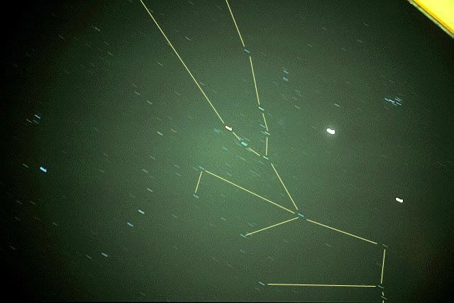
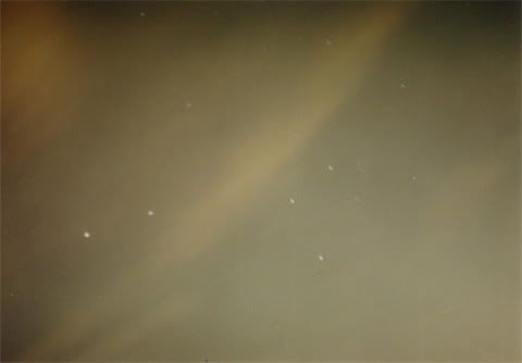
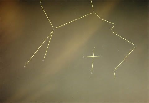
A person trying to photograph the night sky can simply use a camera mounted on a tripod and start taking long exposures from seconds to minutes long. However, due to the rotation of the Earth, and thus movement of the stars across the sky, an overly-long exposure will cause "star trailing" (ie streaks of trails left by the stars). This can be artistic in a sense but for those who wanted to take sharp star-like photos, this is bad.
The Scotch mount is a home-made tracking mechanism which compensates for the star motion by guiding the camera mounted on it to follow the stars in exactly the same rate. In fact, it moves in the same rate as the Earth's rotation, if precisely constructed, but in the opposite direction.
The Scotch mount is a popular project engaged by many astronomers due to its simplicity in construction (depending on the type you are working on), cost-effectiveness as compared to buying a consumer-grade drive system such as those that come with telescopes, and the shear fun and achievement one can get out of making one.
Types of Barn Door Tracker
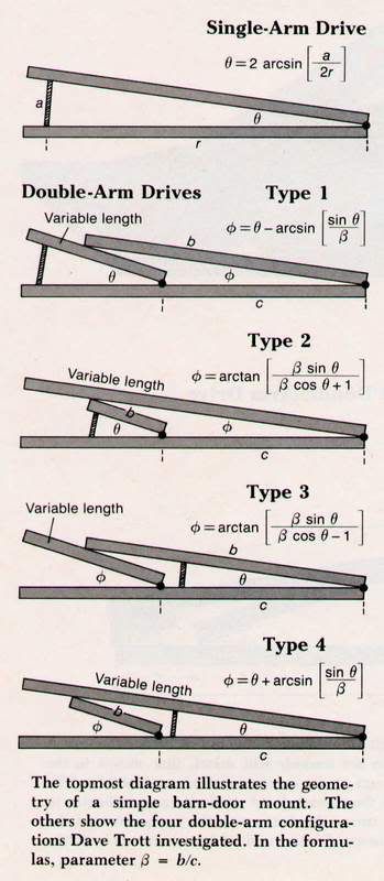
There are many variants of the mount. Every astronomer makes his own version of the gadget to suit his needs and that includes me. However, there are a few basic types. The following images are extracted from http://hometown.aol.com/davetrott/, courtesy of Dave Trott.
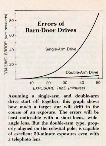
From this image below, we can see that there are 2 general types of mounts, single-arm and double-arm.
The tracker can also be manually driven or motorised using a simple stepper motor circuit. It is basically a trade-off between simplicity of construction, cost, convenience of use and accuracy.
From the image below (courtesy of Dave Trott), we can see that the tracking errors accumulated by the single-arm version will get pretty bad from 10 to 15 mins onwards, while the double-arm designs remain low in error rate for an hour or so.
Construction Details
The tracker I have built is a single-arm manually driven version customized for places, like Singapore, where the polar stars, like Polaris, are not visible anytime of the year due to low latitudes. The design should work
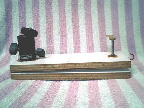
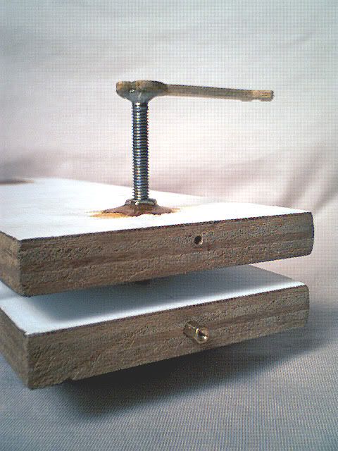
You can see that my tracker is pretty primitive and simple. If you have seen or constructed more advanced versions, you will know I am not joking. Basically, it consists of 2 wooden boards connected together at 1 end using hinges. On 1 end of the top board is a typical ball-head mount to mount your camera. On the other end is the "drive" mechanism. That's it!
 Main Boards
The upper and lower wooden boards came from plywood planks salvaged from trash dumps. ie. they are free! The boards are connected together at one end using simple off-the-shelf cheap hinges that you can easily find in hardware shops.

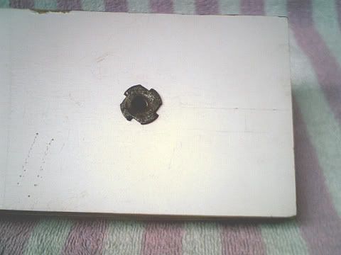
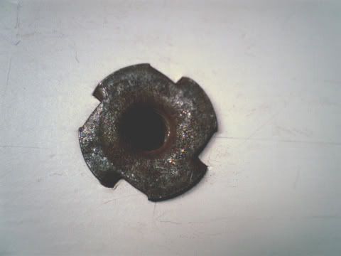
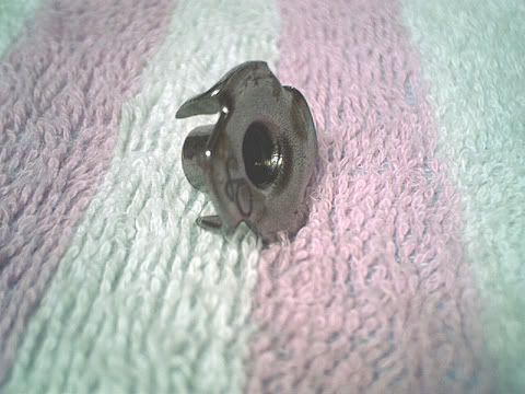
To allow the tracker to be screwed on top of a tripod, a hole at the bottom of the lower board was drilled and a "Tee-nut" was fixed in. The tee-nut has the same diameter of 3/4" and thread as the tripod screw. Pretty cheap too.

Drive Mechanism
The drive mechanism consists of a handle which you must manually turn clockwise at a rate of 1 revolution per minute. This will cause the distance between the 2 boards to increase. The calculations to derive the various figures are as follows. Please refer back to Dave Trott's images on the different tracker designs in the beginning of my article for the exact formula.
The Earth takes 24hr or 1440min to complete a single rotation. To be really precise, the Earth actually takes 23hr 56min 4.1s (a sidereal day) or 1436.068333 min to complete the rotation. So, taking a complete rotation to be 360 degrees, in a minute, the Earth would have rotated only about 0.25 degrees. That means, for every minute, my tracker needs to increase the distance between the upper and lower platform to achieve a 0.25 degrees increase in the angle subtended by the 2 platforms at the hinges.
The bolt at the drive mechanism was chosen to have a thread resolution of 1mm (ie the distance between each thread or line on the screw surface is 1mm). Thus, a single complete rotation of the bolt will move the 2 platforms 1mm apart. A 1-minute rotation rate is chosen out of convenience so that one can easily synchronise the rotation with a minute hand of a watch.
Now we need to derive the distance between the centre of the bolt and the centre of the hinges. This is easily done using simple trigonometry. Dave Trott used "sin" in his illustration. I decided to use a simple tangent formula.
Distance between bolt and hinges = thread resolution / TAN(angle to increase per min)
Distance = 1mm / TAN(0.25) = ~229mm (round off to the nearest mm)
Thus, given these figures, we have achieved a rotation rate pretty close to that of the Earth in the opposite direction.
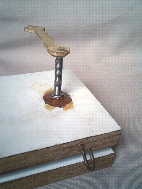
From the photo below, you can see that the drive mechanism is made up of many parts. A wooden handle is glued to a metallic bolt. The nut of the bolt is glued to the upper board using epoxy resin, a superglue consisting of 2 types of liquids mixed together.
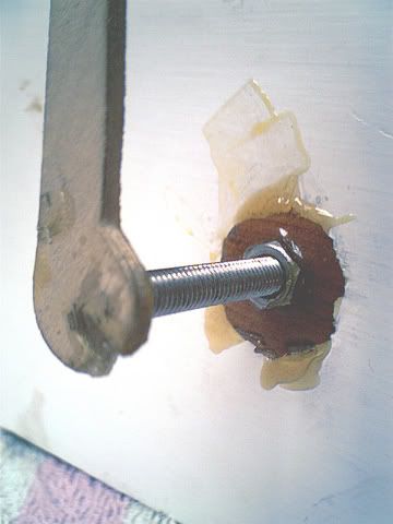
The bolt is also glued to the wooden handle using epoxy resin. The handle is actually a part of a wooden puzzle. Pretty cheap material.
The other end of the bolt is a "cap" (or whatever you would call it) that keeps the mechanism from falling apart as well as preventing scratches to the lower board. It is also glued. The hook at the end of the board is used to hold a heavy object like a small bag. It acts as a counterweight when the camera on the other side is too heavy.
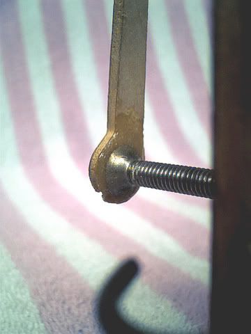
From the following image, you can see the drive mechanism in action after it has been turned many rounds.
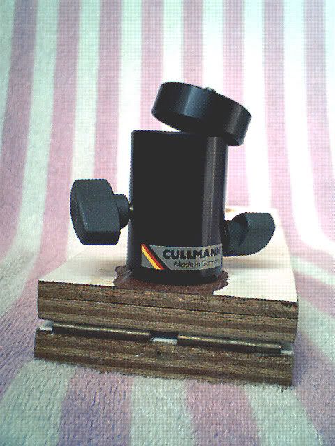
Camera Mount
Originally, I wanted to save construction cost, so I tried to build a cheap camera mount myself using plastic pipes, a wooden ball with a hole in the middle (those used in artwork), a bolt and nut, and a "Y-shaped" screw. (see image below).
The pipe on the left is glued to the upper wooden platform. It is used as a base to hold the rest of the mount.
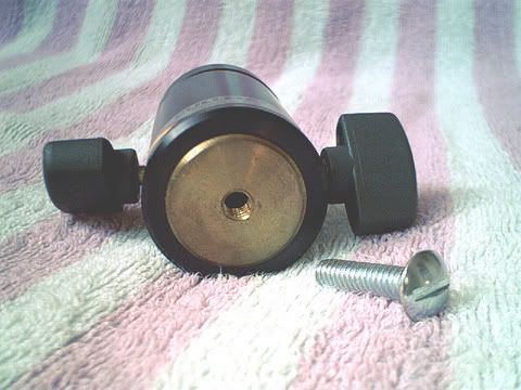
Another pipe sits on top of the base and swivels 360 degrees around it. It also holds the wooden ball above it. A bolt is glued to the wooden ball and has a diameter of 3/4" and a thread suitable for mounting a camera. The ball-and-bolt can move freely as long as the "cap" is not tightened. A "Y-shaped" screw and its nut is used to tighten this pipe to the base.
The "cap" is made up of 2 pipes glued together. A slot is sawed to allow the bolt to be placed horizontally.

On the whole, the home-made mount was stiff while making adjustments. That was also a main source of jerks to the whole setup, which in turn caused the polar alignment to be out. The simple bolt and nut setup couldn't firmly hold the camera in place. Sometimes, the camera would "rotate" due to a shift in the centre of gravity, causing the grip of the nut on the camera to loosen. The epoxy resin used to glue the nut for the Y-screw was weak. Many a times, the nut would "peel off" when I tightened the screw to keep the pipes from shifting.
With all the hassle and disadvantages of this home-made mount, I decided to upgrade to a real camera mount. The camera mount can be easily bought from any decent camera shop. It costs around S$20 to S$40. It allows you to position the camera in any direction quickly and smoothly.
Polar Alignment (1st Version)
The hinges of the tracker must be aligned parallelly to the Earth's rotational axis just like a telescope on an equatorial mount. Other trackers use Polaris (the Northern Polar star) but in Singapore we can't see that star since we are too near to the Equator and the star is always on the horizon, so I have to use another method.
I decided to align the tracker in an altazimuth fashion. That is, alignment by azimuth (horizontal directional bearing w.r.t. Magnetic North) and altitude (degree of vertical inclination w.r.t. the horizon according to your latitude). To achieve this, I needed 2 separate scales, one for azimuth and another for altitude. The reference line used for alignment is the line formed by the 2 hinges.
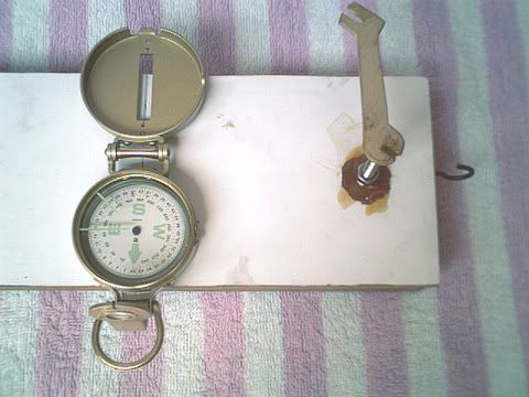
For azimuth alignment, a line parallel to the hinges was drawn in the middle of the upper platform (see images below). A compass will be placed over the line. The entire tracker will be rotated using the tripod's adjustments until the N-S needle of the compass coincides exactly with the line. To make the upper platform open or "rotate" in the opposite direction of Earth's rotation, the compass must point upwards towards north. Actually for very precise alignment, I need to offset the bearing slightly so that I am pointing to the True North and not Magnetic North, but for convenience purposes, I assumed them to be equal. Maybe in future, I will cater for the slight deviation.
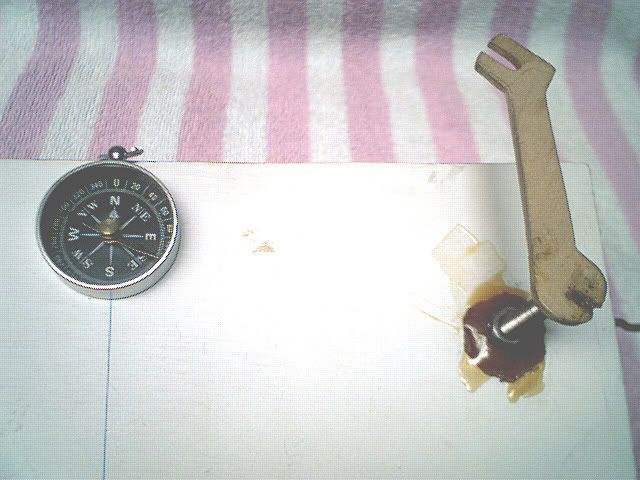
I managed to salvage a lousy compass from somewhere in my house for the purpose of azimuth alignment (see image below).

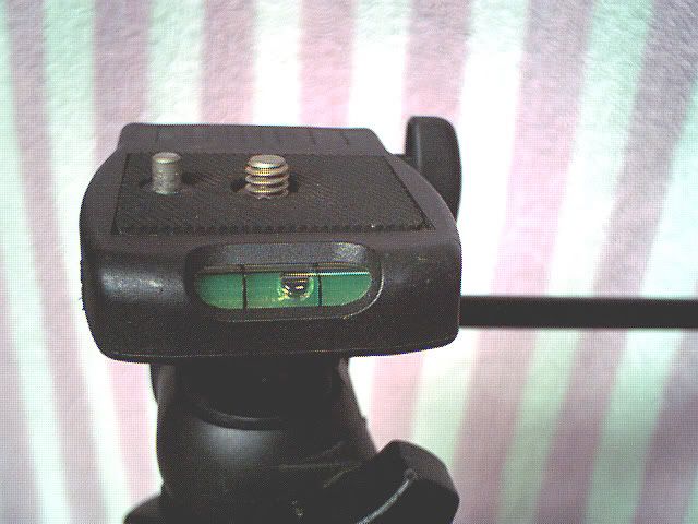
For altitude alignment, to be precise, I actually had to incline the tracker around 1 degrees to the horizon since Singapore is about 1 degree North of the Equator. However, to save cost again, I decided to rely on the "bubble" feature on my tripod. Below are shots of the original tripod I have used which spoilt recently.
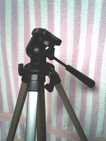
It had a small green tube containing a bubble on the head (see image below). To align it horizontally, I needed to adjust the tripod's head until the bubble consistently stayed in the centre. It was a tedious and painstaking way of aligning. I could never get the bubble to stay still in the middle. The adjustment screws and handles of the tripod were also very rough. A slight jerk would send the bubble to jump about. It took me quite long to get a less-than-satisfactory alignment. Moreover, I wasn't able to achieve the 1 degree altitude alignment required.
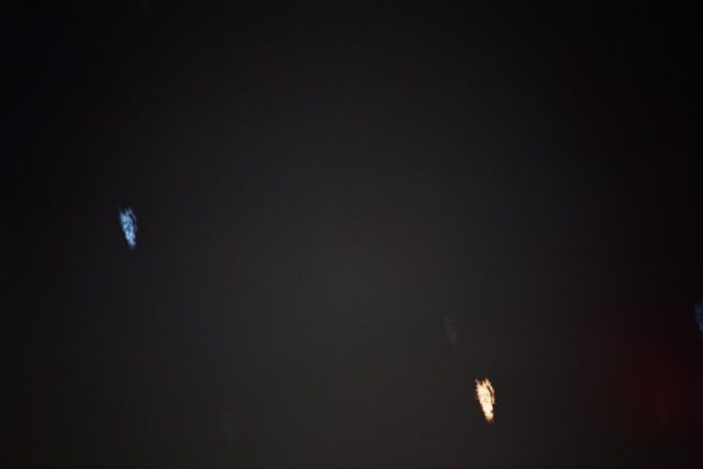
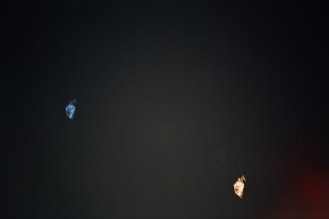
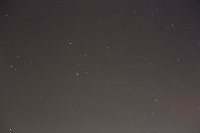
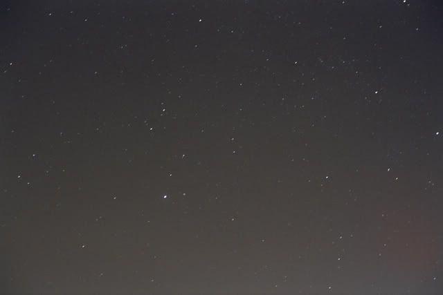
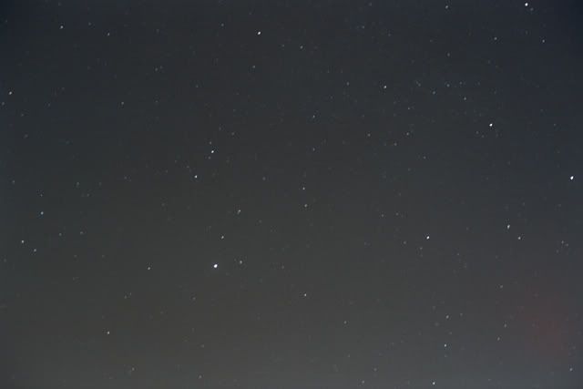
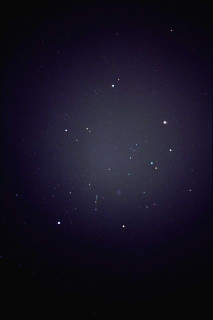
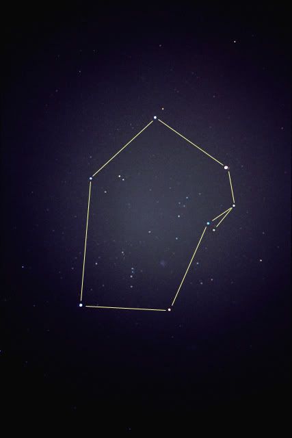
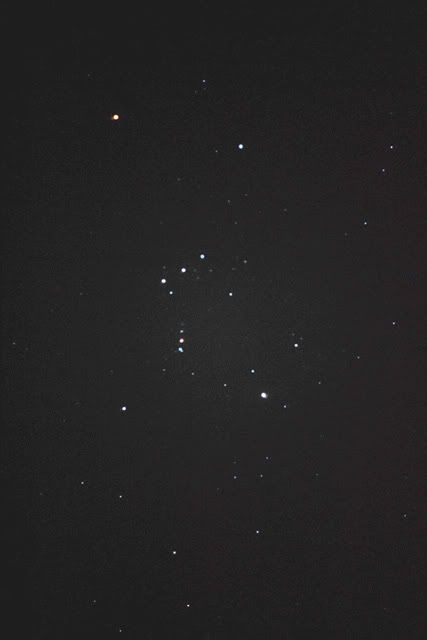
On the whole, the 1st version alignment design was a terrible hassle. It took me 10 minutes or more to get a rough alignment. I also need to constantly check and realign in between shots. However, to my surprise, some of the photos turned out pretty well.
Polar Alignment (2nd Version)
The first version polar alignment design was a hassle to setup and potentially inaccurate. Moreover, the original tripod was spoilt recently. So, I had to get a new and better one. I tried to look out for a sturdy budget tripod with smooth fine adjustments and the bubble mechanism. However, I couldn't find one. So, I decided to forgo the bubble mechanism and focused on sturdiness and smooth adjustments.
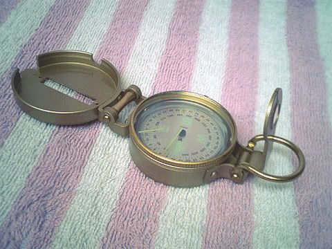
I have also decided to upgrade the old compass. The resolution of the compass reading was coarse and the needle was not stable. That produced poor results sometimes. So I decided to spend S$24 to get a more professional one (see compass below). It has many advantages. The resolution is finer and the rotation of the internal disc is much smoother, which saves me alot of hassle when trying to get a reading. It also has a line on the cap which I can use to align the compass with the line on my tracker. It also has prominent and luminous letters and lines combined with the white background of the disc, which allowed me to easily take readings in a dark place. Finally, I can use this compass for other purposes like trekking.
Without the bubble mechanism in the new tripod, I had to construct my own alignment mechanism. The general idea was to use a protractor, those used for technical drawing in schools, with a simple "pointer". I used easily available and cheap (or free) materials to make it. I shall call it "altitude alignment scale" or "inclination scale". The general idea is that as I tilt the tracker using my tripod, the swinging needle will indicate the angle of inclination from the protractor. Below a shot of the final look.
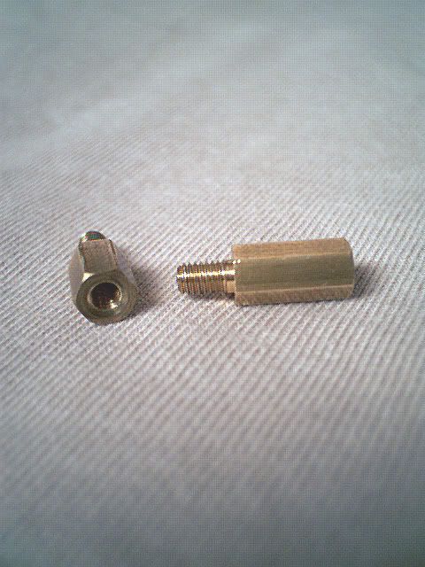
To start, a special screw was screwed tightly into the lower platform. This will allow more screws to be screwed in.
The special screw is actually a little brass screws used in computers to screw the computer motherboard to the casing. I salvaged many of such screws from old computers mainly because I was also interested in computer DIY assembly. Here are how such screws look like.
The picture of a complete scale component is shown below:
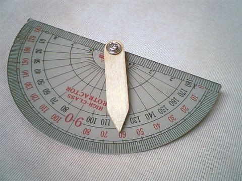
It is made up of 2 main parts. First, a normal plastic protractor which students use to draw geometric figures in schools. A hole is drilled at the centre of the semicircle for the screw and nut.
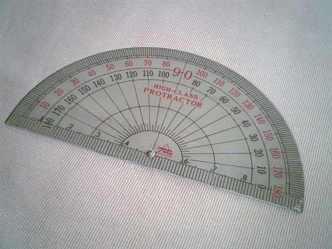
To help me see the markings more clearly in the dark, I sprayed a light-coloured paint on the reverse side of the protractor. The paint was actually used to paint model vehicles. I once tried to pick up model-making years back but gave up very soon and I was left with a useless can of paint. The worksmanship wasn't too good as there were smudges here and there but it will do.
The second part of the scale was its "needle" or pointer to indicate the degree of inclination.
It was again made up of cheap or free stuff. The needle was made from an ice cream stick which you can easily get from any stationery or arts-and-craft shop. You just need to drill a hole for the screw, saw it to the desired length and file up the sharp pointer end. The screws and nuts are again from old computers. The hole is larger than the screw so that the needle can swing freely.
To ensure that the needle accurately indicates the degree of inclination, it must be accurately made. The hole for the screw must be as close to the centre of gravity of the stick as possible. The same goes for the sharp pointing end. If not, a wrong centre of gravity will cause the needle to tilt, giving rise to false readings. This was my 3rd attempt. Previous 2 attempts were failures due to the lack of worksmanship.
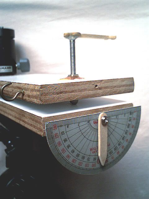
Below is how the whole scale is fitted onto the platform.
The nut keeps the protractor tightly in place. The protractor is aligned horizontally with the lower platform. The screw is not screwed in totally to allow the needle to swing freely as the tracker tilts. The distance between the needle and the protractor is kept small to minimise parallax errors while taking readings.
The new scale was more accurate and easier to use than the bubble. Combined with the smoother adjustments of my new tripod, I was able to meet the 1-degree inclination requirement. The smooth tripod adjustments also reduced jerks and that shortened the time required for me to setup the tracker. Using the screw system, the scale component can be easily detached for storage and transportation. It can also be easily reused in another tracker.
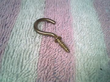
Counter-Weight Hook
Here's a closer look at the counter-weight hook. It is also a cheap hook you can find in normal shops.
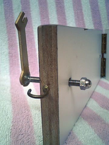
As a recap, the 1st version design of the hook placed it at the very end of the upper platform (see image below). Its purpose is to prevent the upper board from flinging open when the camera setup at the other end becomes too heavy. Anything can be used as a counter-weight such as torch, bags, handphones, etc.
In the 2nd version, the hook was moved to the side to make way for the new inclination scale.
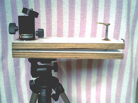
The Complete Setup (1st Version)
Here's a shot of the 1st version tracker with the original tripod.
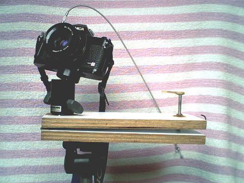
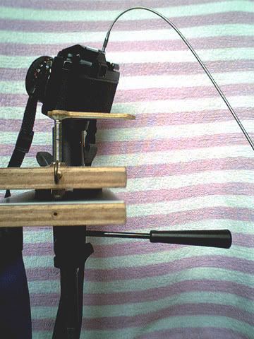
Here's a shot of the tracker with my Yashica manual SLR, 50mm standard lens and mechanical cable release. The cable release is used to remotely press the shutter button so as to minimise vibrations during the shots.
Here's a sideview of the setup. From this angle, you can see that the handle of the tripod is used to adjust the inclination of the tracker with the help of the green tube.
Other Accessories
During field trips, I need to bring along other accessories. Ideally, I need to an analog watch with a minute hand so that I can synchronise the hand's movement with the turning of the drive handle. In occasions where I only had a digital watch, I had to estimate the amount to turn from the time itself. I also brought along my pocket astronomy guidebook with a mini starchart inside to help me locate constellations and objects. To provide minimal lighting, I brought along a red torch. Red light reduces glare on the eyes. Finally, I would bring along a pair of binoculars at times to help me locate smaller sky objects.
Working on a Dual-Arm Motorised Version
Although the single-arm manual tracker is moderately sufficient for up to 10 minutes of long exposures, manually driving the tracker can be a tiring task. I need to focus on both the watch as well as turning the handle. Most of the time, I also need to keep the cable release pressed. This can be quite a brain taxing task. For shots longer than 10 minutes, this can be an impossible task. So, I have initially planned to work on a dual-arm motorised version to allow me hassle-free accurate long exposures up to 1 hour.
After the initial planning, survey and designing, I bought some materials.
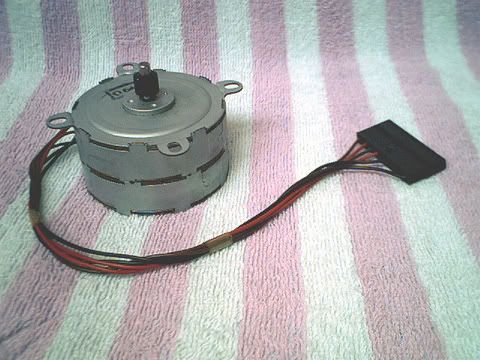
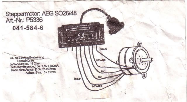
Below is a stepper motor that supposedly turns 48 steps per revolution. By right, I need to achieve the same turning rate as that in the manual version, that is 60 steps per revolution, which is in sync with the 60 seconds of a minute hand. To do so, I need to use a correct combination of gears to step it down to the 60-step turning rate. A controller chip and other peripheral electronic chips are also required to drive the motor. I couldn't find the controller chip in the shops. I also need a 12v DC power supply to drive the motor. This can either be a series of 8 consumer 1.5v batteries or a 12v lead acid battery.

Here are some other small items I have bought or found. The gear was supposedly found somewhere. The battery cable was actually meant for a 9v rectangular battery. The bolt and nut are leftovers from the 1st version. The others are bits and pieces of electronics I have bought such as switch, resistors, transistors, chips, capacitors, etc. I have also bought a circuit board, a soldering iron, a multimeter and a solder sucker.

I would also need to find more wooden planks for the actual construction. I salvaged some of the leftover wood from the 1st version and started working on a few parts. However, due to the lack of important raw materials like the stepper motor controller, I had decided to postpone the work until a later time.
Conclusion
The entire project was quite a success. The completed tracker provided me with the opportunity to take guided astrophotographs for up to 10 minutes long within a tight budget. It also helped me to gain knowledge and experience in astrophotography, electronic circuitries, carpentry and other skills. Although this manual version has some limitations, it will sufficiently fuel my interest in astronomy until I complete my dual-arm motorised version or get a professional equipment. On the whole, it was a fun and learning experience.
References
Finally, some external references. You might like to take a look at them to find one suitable to your needs. Many of them are much better than mine.
http://hometown.aol.com/davetrott/
http://www.astronomyboy.com/barndoor/
http://www.jlc.net/~force5/Astro/ATM/Barndoor/barndoor.html
http://www.skynewsmagazine.com/pages/resources/barndoor.html
http://www.fayettevillenc.com/special/backyard/barn.htm
http://www.tucsonastronomy.org/barndoor.html
http://www.angelfire.com/stars2/bwolfe/BarnDoor.htm